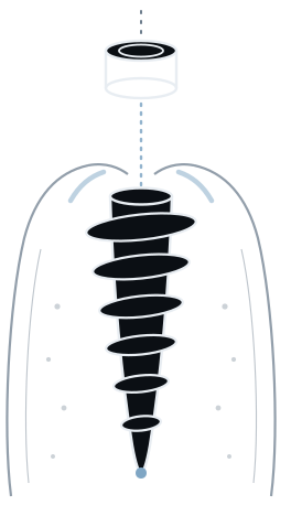
Upper first molar, out and replaced in one visit.
Site 16 taken from failing tooth to placed implant at a single appointment — primary stability drawn from the interradicular septum, and a patient-specific healing abutment made before the extraction.
The case
An upper right first molar, failing and due to come out. Rather than extract, wait,
graft and come back, the tooth was removed and the implant placed at the same visit
— with the emergence profile already made and waiting.
The problem with a molar socket
A fresh molar socket is the hardest place in the mouth to take primary stability from.
The socket is wider than any implant that belongs in it, the walls are thin, and the roots
have just left three separate holes behind. Whatever holds the implant on the day has to
come from somewhere other than the socket walls.
What is left is the interradicular septum — the wedge of bone between the roots
— together with whatever native bone sits apical to it. It is a small target, and it
is why immediate molar placement is classified by septum anatomy rather than by tooth:
Smith and Tarnow’s Type A, B and C sockets describe exactly this, whether the septum can
house an implant, whether it can only partly engage one, or whether nothing can be taken
from it at all.
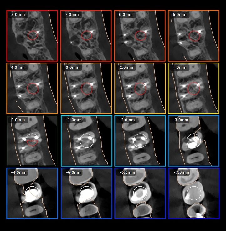
That classification is the first question of the plan. It is answered on the CBCT,
before anything is extracted.
The plan's answer
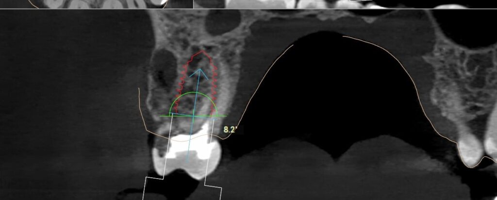
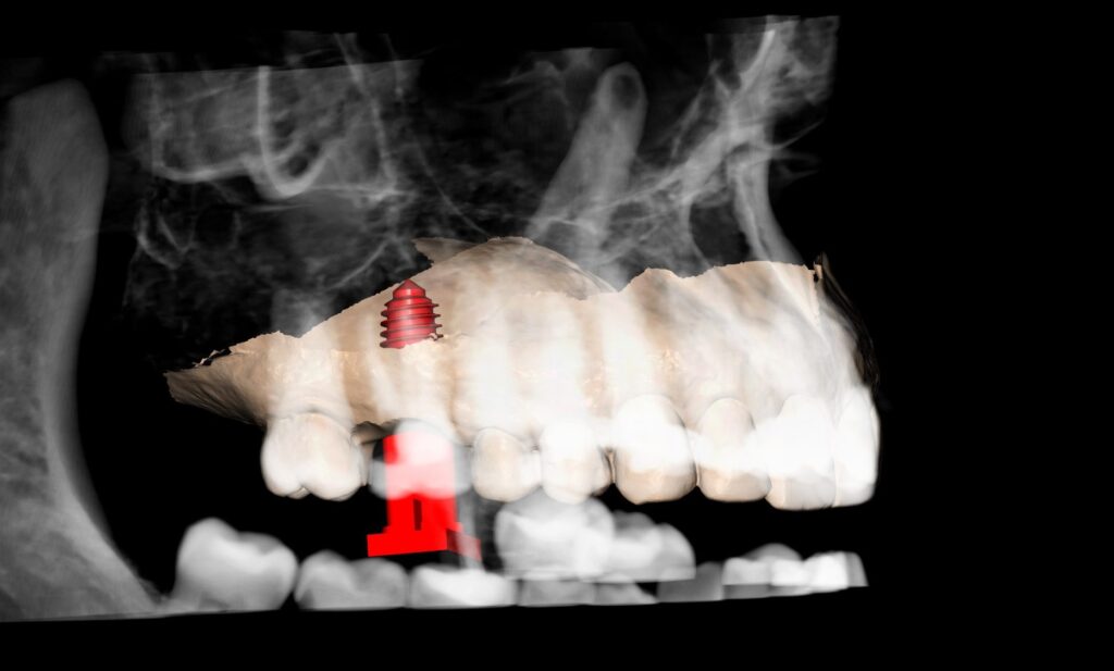
A Ø 6.0 mm implant, chosen so its threads engage the septum rather than spinning
in the void of the socket. Diameter here is not a prosthetic decision; it is about finding
the only bone available and taking hold of it.
The septum’s width and height are measurable before the tooth comes out. Either a 6.0
engages it or it does not — and that is a question far better answered on screen than
with the socket open and the patient waiting.
The patient-specific healing abutment
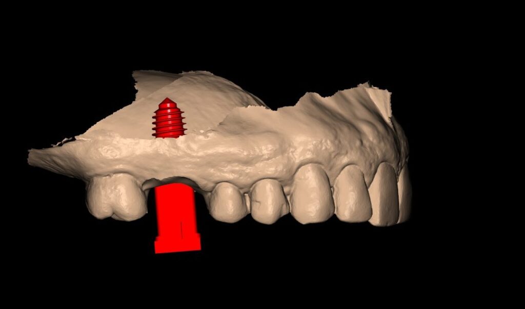
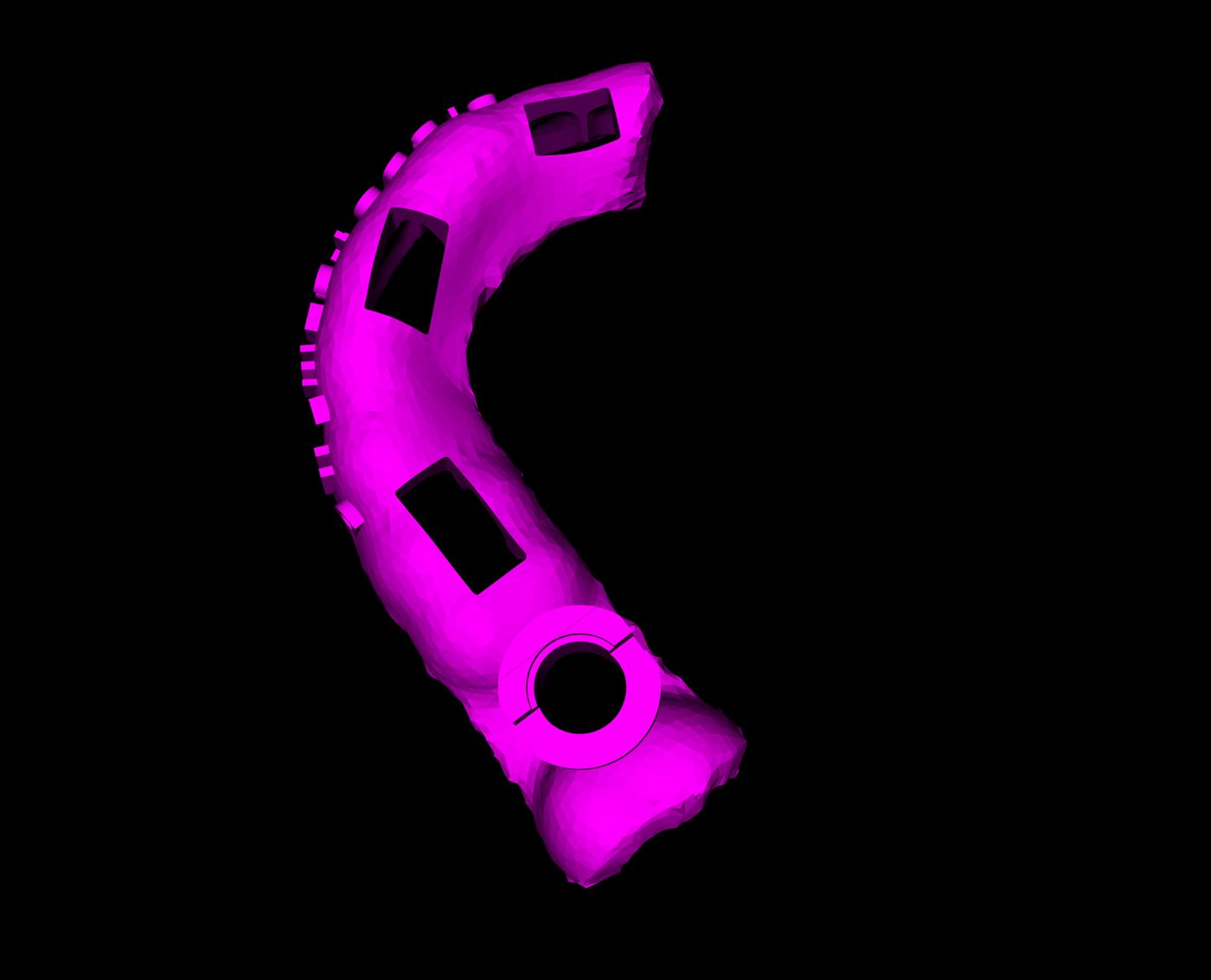
The part of this case worth copying: the healing abutment was made by the laboratory
before the surgery, from the same plan the guide came from.
So the sequence on the day was extract, place, and seat a healing abutment that already
carried the right emergence shape — rather than a stock cylinder, which lets the
tissue collapse toward a round profile that a later provisional then has to push back
out.
What that is documented to achieve, and what it is not: randomised trials comparing
patient-specific with conventional healing abutments at immediate placement report better
preservation of soft tissue volume and papilla height, higher pink esthetic scores, and
less discomfort at crown insertion. The same trials found no difference in marginal bone
level at six to twelve months, and the evidence base remains small and short-term. So this
is a soft-tissue and comfort argument, made honestly — not a bone-preservation
claim.
It also costs no extra chair time, because the component was made before anyone sat
down.
System and software
| Site | Tooth | Fixture ref | Diameter | Length |
|---|---|---|---|---|
| 16 | Upper first molar | FALIHX6010 | Ø 6.0 mm | 10 mm |

Outcome
| Site | Insertion torque | ISQ |
|---|---|---|
| 16 | 95 Ncm | 93 |
In one line
A failing upper molar replaced at the same appointment, with the diameter chosen against
a measured septum rather than a hope, and the emergence profile made before the tooth came
out.
References
Smith RB, Tarnow DP. Classification of molar extraction sites for immediate
dental implant placement. Int J Oral Maxillofac Implants 2013;28(3):911–916.
Ragucci GM, Elnayef B, Criado-Cámara E, et al. Immediate implant placement in molar
extraction sockets: a systematic review and meta-analysis. Int J Implant Dent
2020;6:40.
Graf T, et al. Systematic review of peri-implant conditions and aesthetic outcomes of
customized versus conventional healing abutments. Int J Implant Dent
2024;10(1):61.
Chokaree P, et al. J Clin Med 2024;13(3):886. — Elgendi MM, et al.
BMC Oral Health 2025;25:83.