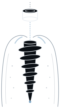
Three implants, upper right.
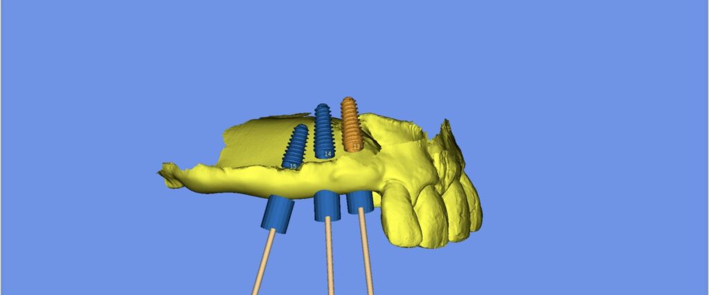
Sites 13, 14 and 15 restored under a low sinus floor — planned in SMOP, placed flapless through a tooth- and tissue-supported open template, and in function the same day.
The case
A three-unit bounded gap in the upper right quadrant: canine, first premolar and
second premolar — FDI 13, 14 and 15 — all missing, restored with three
implants.
The maxillary sinus floor sits low over the posterior sites. That makes depth the
constraint that governs the case: there is room for the implants, but not much room
for error in the apical direction. Fixing depth in the plan, and holding it with a
guide that cannot ride up, is what turns that from a judgement made freehand under
irrigation into a number decided at the planning stage.

Why this guide
Two things drove the design.
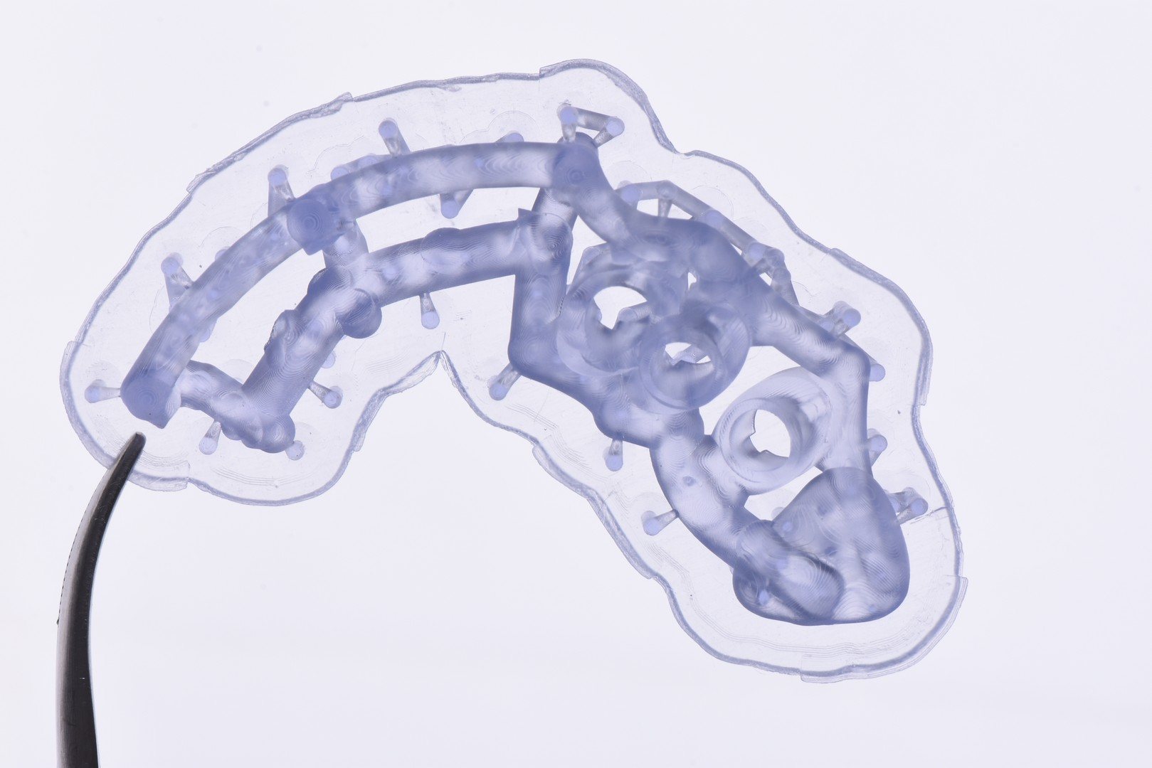
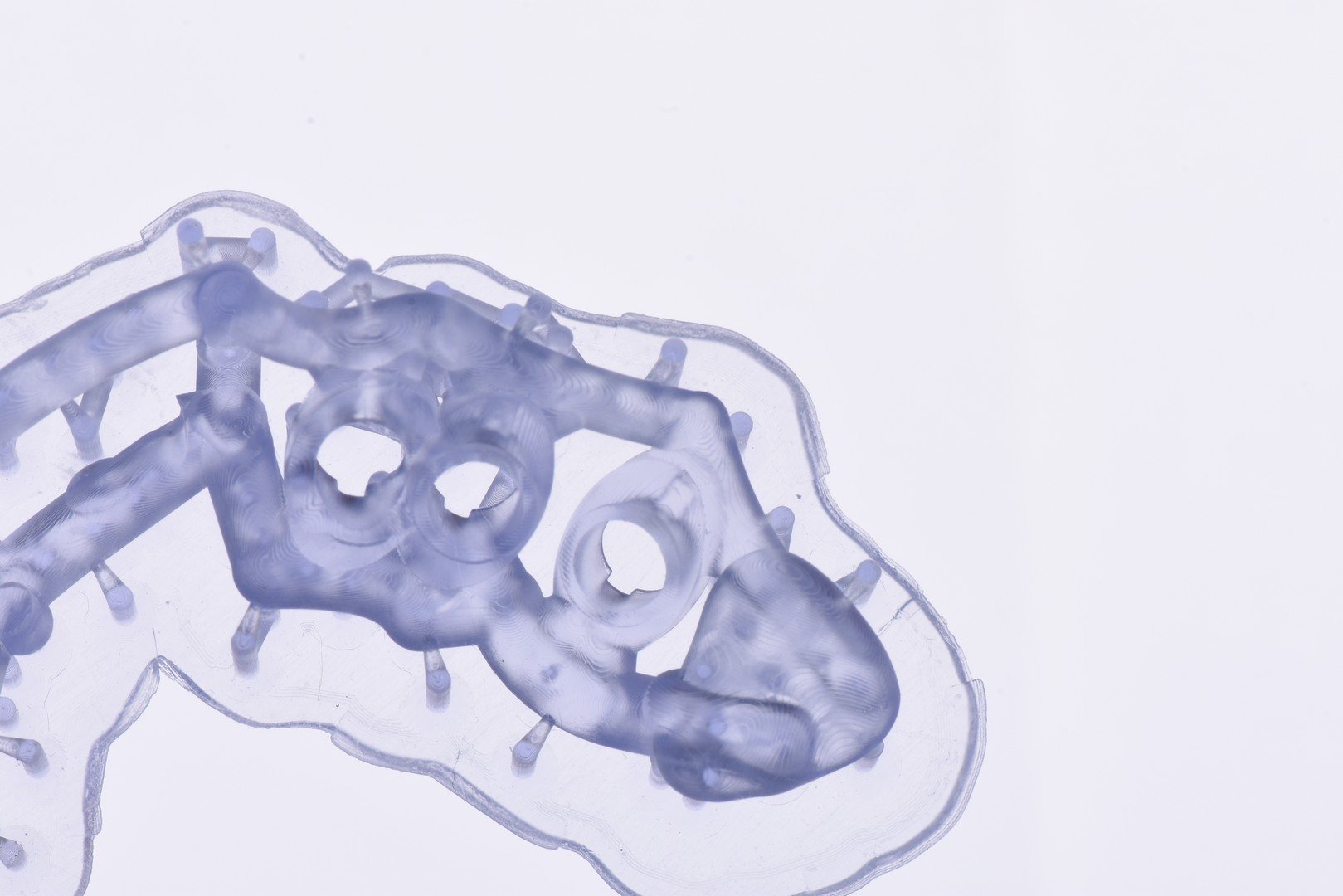
The span. Three consecutive missing teeth leave the middle of the
template with nothing beneath it. A guide resting only on the abutment teeth at either
end behaves like a bridge under load, and any flex there is transferred straight into
the osteotomy as angular error. Adding tissue support across the edentulous ridge takes
that flex out. The remaining teeth still give the template its seating position and its
rotational reference; the ridge stops it from deforming between them.
Verification. An open template leaves the osteotomy visible while it
is being cut. You can confirm the drill is running where the plan put it, irrigate
directly into the site rather than relying on coolant finding its way down a closed
sleeve, and check that the guide is fully seated at the moment it matters rather than
inferring it from the outside.
Flapless
The surgery was performed flapless — no incision, no reflection, no sutures.
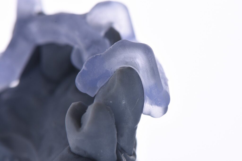
This is where the hybrid support earns its keep. The standing objection to operating
flapless through a guide that rests on mucosa is that mucosa is compressible: press the
template down and it seats a little deeper than it did on the model, and that error goes
straight into implant depth in a case where the sinus floor has already set the limit. A
template supported only by tissue cannot tell you how hard you pressed.
Here it does not have to. The remaining teeth mesial and distal to the gap are what set
the seating position — they are rigid, they cannot compress, and the template either
sits down on them or it does not. The ridge contact across the span is there to stop the
guide flexing between those two supports, not to determine how deep it sits.
Tooth support fixes the vertical; tissue support removes the bend. That
combination is what makes it defensible to place three implants under a sinus without ever
seeing the bone.
The implants
| Site | Tooth | Fixture | Diameter | Length |
|---|---|---|---|---|
| 13 | Canine | AnyRidge 4011 | Ø 4.0 mm | 11.5 mm |
| 14 | First premolar | AnyRidge 4011 | Ø 4.0 mm | 11.5 mm |
| 15 | Second premolar | AnyRidge 4010 | Ø 4.0 mm | 10.0 mm |
Outcome
| Site | Insertion torque | ISQ |
|---|---|---|
| 13 | 60 Ncm | 84 |
| 14 | 67 Ncm | 89 |
| 15 | 64 Ncm | 89 |
Planned, then placed
A plan is a claim. The post-operative radiograph is where the claim is either kept or
it is not — and it is the only part of a guided case that a sceptical colleague
will actually accept as evidence.
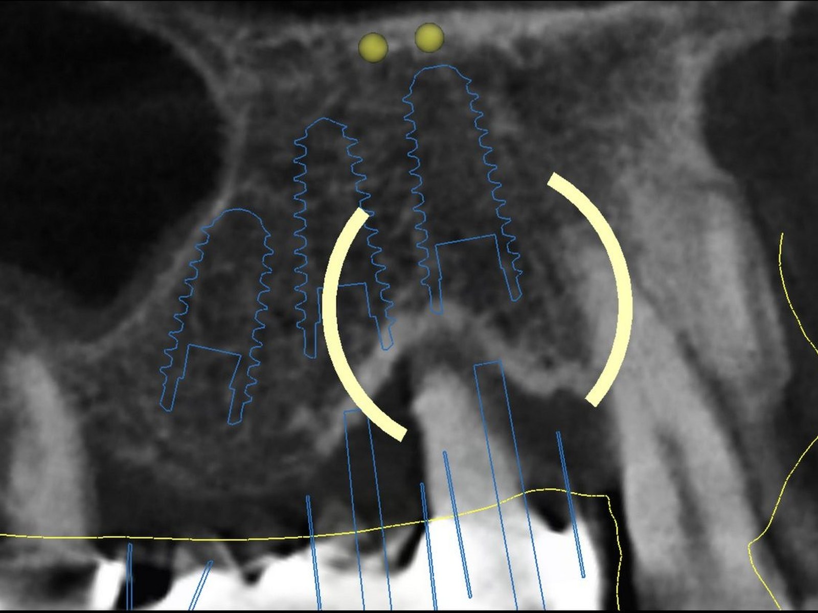
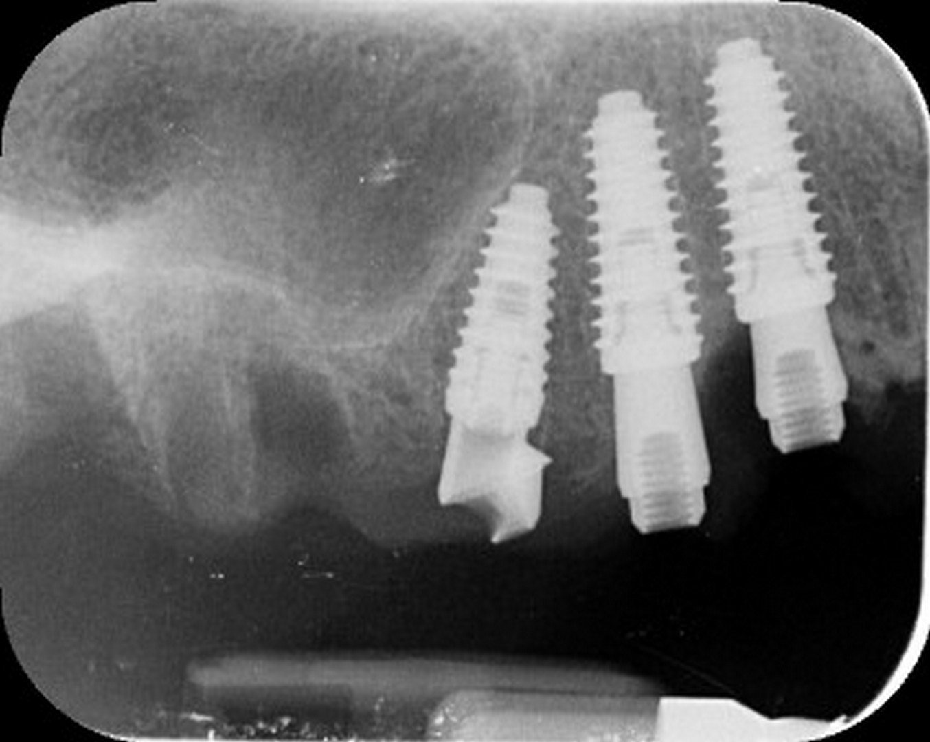
So here they are side by side: the same three sites, the same anatomy, first as
intended and then as delivered. Three implants at 13, 14 and 15, each one seated at the
depth the plan specified, the posterior implant stopping short of the sinus floor exactly
where it was told to, multi-unit abutments in place and ready to carry the provisional
the same day. No flap was raised to achieve it.
In one line
Three implants in soft posterior maxillary bone under a low sinus, placed through a
guide without raising a flap, and in function the same day — because the depth, the
axis and the prosthetic platform were all settled on screen before the patient sat down.